Gem #4: PWM Position Control for Radiocontrol Servos
by Michael Gonzalez Harbour —Universidad de Cantabria, Spain
Let's get started…
Introduction
Pulse Width Modulation (PWM) is a common mechanism for encoding analog information on a digital line, and is commonly used in control signals. It consists of generating pulses on the digital line. The width of the pulse, i.e., the time interval during which the signal is high (or low), is proportional to the analog value that is used as a control signal.
The servos used in radiocontrol systems such as model cars or airplanes are usually based on a PWM signal in which a periodic pulse with a period between 10 and 30 ms is generated. The width of this pulse varies between 1 and 2 milliseconds, and represents the angular position of the servo mechanism. A pulse of 1 ms represents one extreme of the angular position, 2 ms represents the other extreme, and 1.5 ms represents the central position. Four such pulses may be issued in each period to control four different servos.
The timing of the pulses has to be very precise. If we have a range of rotation of the servo between -120 and 120 degrees, and we want a precision of, say 1 degree, this means that the precision in the timing of the pulse must be 1ms x 1/240 = 4.1us. This precision can only be achieved if we use an Ada run-time system that runs on top of a Real-Time Operating System (RTOS) for a bare machine, such as MaRTE OS (http://marte.unican.es)
In our system we have two servos controlling two axes and using separate digital signals. We want to control the position of these servos from a computer running an Ada 2005 program, and generating the pulses through a digital output port.
Since this is an example application meant for showing the real-time features in Ada 2005 and for testing purposes, we will implement it using the GNAT implementation on top of Linux, using the MaRTE OS run-time system. This implies that we cannot get a time resolution better than that offered by Linux (around 10 ms by default). For this reason we will modify the timing requirements of the system by multiplying all the time intervals by a factor of 100. This implies a period of 2000 ms, and pulses of duration between 100 and 200 ms, for an accuracy of only 24%. This would not be acceptable for a real implementation (for which an RTOS would be necessary), but is OK for our testing purposes.
Digital output port
The digital output port is implemented in package Digital_Output, which has a Set operation to set the desired port to a digital value Low or High, and an operation to close the device. Opening of the device is automatic.
package Digital_Output is

   -- Identifier of a digital output line
   type Channel_Id is range 1..2;

   -- Digital output value
   type Digital_State is (Low, High);

   --------------------------------------------------------------------
   -- Close
   --------------------------------------------------------------------
   --
   -- This procedure must be called once the package is no longer to
   -- be used, to close the output device

   procedure Close;


   --------------------------------------------------------------------
   -- Set
   --------------------------------------------------------------------
   --
   -- This procedure sets a particular digital channel to the given
   -- digital value

   procedure Set (Channel : Channel_Id; To : Digital_State);

   --------------------------------------------------------------------
   -- Get
   --------------------------------------------------------------------
   --
   -- This function returns the digital value of a particular channel

   function Get (Channel : Channel_Id) return Digital_State;

end Digital_Output;
The implementation of this package is a simulated environment in which the changes to the values of the digital outputs are recorded together with the time at which they occur, relative to the start time of the experiment. When the device is closed, the recorded values are written to a text file, whose contents can then be displayed using a graphical representation program such as gnuplot.
Architecture of implementation
The implementation of the servo control mechanism is made in package PWM. This package contains a protected object called Servo_Control that stores the position desired for the servos and implements the operations required to change the position and generate the timing for the pulses that are necessary to control the servos by PWM.
The timing of the pulses to be generated is controlled from Ada 2005 timing events. Each servo has its own timing event, which is programmed to be triggered at the time when the pulse must start, and subsequently when it has to stop. The position of the servo is shared between the timing event handler and the user task or tasks that write the desired positions. This sharing is correctly protected through the use of the Servo_Control protected object.
The specification of the PWM package is
with System;
with Ada.Real_Time;
with Ada.Real_Time.Timing_Events;

package PWM is

   package Timing_Events renames Ada.Real_Time.Timing_Events;

   ----------------------------------------------------------------
   -- Configuration constants
   ----------------------------------------------------------------

   Angular_Range       : constant:= 240.0;         --degrees
   Min_Pulse_Width     : constant Duration:=0.100; --seconds
   Max_Pulse_Width     : constant Duration:=0.200; --seconds
   Central_Pulse_Width : constant Duration:=
     (Max_Pulse_Width+Min_Pulse_Width)/2.0;
   Pulse_Period        : constant Duration:=2.000; --seconds

   ----------------------------------------------------------------
   -- Identifier of each of the two servo mechanisms
   ----------------------------------------------------------------

   type Servo_Id is (Steering, Throttle);

   ----------------------------------------------------------------
   -- Angular position of a servo mechanism (in degrees)
   ----------------------------------------------------------------

   type Position is digits 5
     range -Angular_Range/2.0 .. Angular_Range/2.0;

   ----------------------------------------------------------------
   -- Extension of the Timing_Event tagged type to store an
   -- additional attribute with the servo Id
   ----------------------------------------------------------------

   type Servo_Timing_Event is new Timing_Events.Timing_Event with record
      Id : Servo_Id;
   end record;

   ----------------------------------------------------------------
   -- Values of this type represent the positions of several servos
   ----------------------------------------------------------------

   type Servo_Position is array (Servo_Id) of Position;

   ----------------------------------------------------------------
   -- Values of this type represent time values associated with
   -- the servos
   ----------------------------------------------------------------

   type Servo_Time is array (Servo_Id) of Ada.Real_Time.Time;

   ----------------------------------------------------------------
   -- Protected object used to store the desired poritions for the
   -- servos
   ----------------------------------------------------------------

   protected Servo_Control is

      -------------------------------------------------------------
      -- Set the position of a given servo to the given value
      -------------------------------------------------------------

      procedure Set_Position(Id : Servo_Id; Pos : Position);

      -------------------------------------------------------------
      -- Initiate the control actions on a servo
      -------------------------------------------------------------

      procedure Init (Id : Servo_Id);

      pragma Priority(System.Interrupt_Priority'Last);

   private

      Commanded_Position : Servo_Position:=(0.0,0.0);
      Pulse_Start_Time : Servo_Time;

      -------------------------------------------------------------
      -- Start the pulse on one of the servo outputs
      -------------------------------------------------------------

      procedure Start_Pulse (Event : in out Timing_Events.Timing_Event);

      -------------------------------------------------------------
      -- Finish the pulse on one of the servo outputs
      -------------------------------------------------------------

      procedure End_Pulse (Event : in out Timing_Events.Timing_Event);

   end Servo_Control;

end PWM;
We can see that we have defined the pulse duration and period with configurable constants. We have extended the Timing_Event tagged type to add information that is needed in the handlers. This information is the identifier of the servo that is being controlled. The Servo_Control protected object has two public operations. One to set the desired position, and another one to initiate the PWM control on the desired servo. The ceiling of the protected object is set to the interrupt priority level, as timing events execute at that priority.
The private part of the protected object contains the shared state consisting of the desired positions and the time at which the pulse of each servo starts, which is needed to trigger the periodic timing event. It also contains the operations that will be used as handlers for the timing events. One to start the pulse on a given servo, and the other one to stop it. The particular servo Id is stored in the extended part of the Timing_Event object (a Servo_Timed_Event object must be passed for this purpose).
As an implementation alternative, we could have used a single timing event to generate the pulses for both servos, but in that case we would have to implement the arithmetic needed to determine which servo had an earlier start or stop time. By using one timing event per servo we simplify the application code.
Detailed implementation
The body of the PWM package is shown next, and illustrates the usage of the timing events.
with Digital_Output;

package body PWM is

   use type Ada.Real_Time.Time;

   -- Mapping between servo Id and digital channel
   Digital_Channel : constant array(Servo_Id) of
     Digital_Output.Channel_Id := (Steering => 1, Throttle => 2);

   -- Timed events, one per servo
   Timer : array(Servo_Id) of Servo_Timing_Event;

   -------------------
   -- Servo_Control --
   -------------------


   protected body Servo_Control is

      ------------------
      -- Set_Position --
      ------------------


      procedure Set_Position (Id : Servo_Id; Pos : Position) is
      begin
         Commanded_Position(Id):=Pos;
      end Set_Position;

      ----------
      -- Init --
      ----------


      procedure Init (Id : Servo_Id) is
      begin
         Pulse_Start_Time(Id):=Ada.Real_Time.Clock;
         Timer(Id).Id:=Id;
         Start_Pulse (Timing_Events.Timing_Event(Timer(Id)));
      end Init;

      -----------------
      -- Start_Pulse --
      -----------------


      procedure Start_Pulse (Event : in out Timing_Events.Timing_Event) is
         Pulse_Stop_Time : Ada.Real_Time.Time;
         Id : Servo_Id:=
           Servo_Timing_Event(Timing_Events.Timing_Event'Class(Event)).Id;
      begin
         -- Start the pulse on the corresponding channel
         Digital_Output.Set(Digital_Channel(Id),Digital_Output.High);

         -- Calculate the stop time
         Pulse_Stop_Time:=Pulse_Start_Time(Id)+
           Ada.Real_Time.To_Time_Span
           (Duration(Float(Commanded_Position(Id)/Angular_Range)*
                     Float(Max_Pulse_Width-Min_Pulse_Width))+
            Central_Pulse_Width);

         -- Program the timed event for the next stop time
         Timing_Events.Set_Handler
           (Event,Pulse_Stop_Time,End_Pulse'Access);
      end Start_Pulse;

      ---------------
      -- End_Pulse --
      ---------------


      procedure End_Pulse (Event : in out Timing_Events.Timing_Event) is
         Id : Servo_Id:=
           Servo_Timing_Event(Timing_Events.Timing_Event'Class(Event)).Id;
      begin
         -- Stop the pulse on the corresponding channel
         Digital_Output.Set(Digital_Channel(Id),Digital_Output.Low);

         -- Program the timed event for the next start time
         Pulse_Start_Time(Id):=Pulse_Start_Time(Id)+
           Ada.Real_Time.To_Time_Span(Pulse_Period);
         Timing_Events.Set_Handler
           (Event,Pulse_Start_Time(Id),Start_Pulse'Access);
      end End_Pulse;

   end Servo_Control;

end PWM;
The package body contains a constant array that specifies the mapping between servo id and its associated digital output channel. It also contains the timing events, one for each servo, of the type Servo_Timing_Event, which contains the additional servo Id, to be set by the Init operation.
The operations of the Servo_Control protected object have the following behavior:
Set_Position:changes the desired position of the specified servo.Init:sets the Id value in the timing event, stores the pulse start time, and calls theStart_Pulseoperation for the timing event associated with the specified servo.Start_Pulse:this operation starts the pulse on the digital output, then calculates the stop time for the pulse according to the desired position of the corresponding servo, and reprograms the timing event to expire at the stop time, setting theEnd_Pulseoperation as the handler.End_Pulse:this operation stops the pulse on the digital output, then calculates the new pulse start time by adding the period to the previous one, and reprograms the timing event to expire at the start of the next period, setting theStart_Pulseoperation as the handler.
The idea is that after the Init operation is invoked by the application once, the first pulse is started and then the timing event is programmed and will successively invoke End_Pulse, then Start_Pulse, then End_Pulse, and so on, without further intervention of the application.
Test program
We have written a small test program that sets the position of the servos and initiates the PWM control for both servos, then waits for some time and sets the positions to different values, and then waits some additional time before finishing the experiment. The results of the experiment are stored in a text file called pmw_data.txt, which is then plotted.
The code of the text program follows.
with Pwm;
with Digital_Output;

procedure Test_Pwm is
   use type Pwm.Position;
begin
   -- Set initial position and start the PWM control
   Pwm.Servo_Control.Set_Position(Pwm.Steering,100.0);
   Pwm.Servo_Control.Set_Position(Pwm.Throttle,-100.0);
   Pwm.Servo_Control.Init(Pwm.Steering);
   Pwm.Servo_Control.Init(Pwm.Throttle);

   -- Change position after some time
   delay 3.0;
   Pwm.Servo_Control.Set_Position(Pwm.Steering,0.0);
   Pwm.Servo_Control.Set_Position(Pwm.Throttle,100.0);

   -- Let the experiment run for some time and then close it
   delay 20.0;
   Digital_Output.Close;
end Test_Pwm;
The program is built by compiling the main program, test_pwm.adb, with the MaRTE run-time system that implements the timed events:
gnatmake --RTS=rts-marte test_pwm.adb
Results
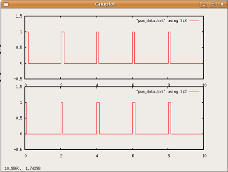
The execution of the program generates a text file with three columns, representing the time since the start of the program, the state of digital output 1, and the state of digital output 2.
The figure below shows the results of the execution. We can see that for the first two pulses the width of the first servo (on top) is larger than for the second one, which corresponds to the initial desired positions. After 3 seconds the positions are changed, and then the width of the pulse of the second servo is smaller.
The results show the expected behavior for the timing events, effectively implementing the desired PWM servo control.
Related Source Code
Ada Gems example files are distributed by AdaCore and may be used or modified for any purpose without restrictions.
gem_4.ada